75 Full Wave Rectifier Diagram For Motorcycle
And they cost a lot more than 2000 now. Increase engine speed till ammeter reads 20 amps.
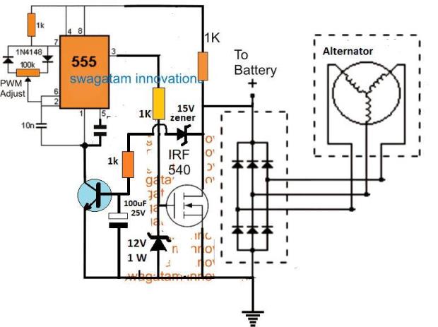
Motorcycle Mosfet Full Wave Shunt Regulator Circuit Homemade Circuit Projects
Thus a full wave rectifier is much more efficient double than a half wave rectifier.

75 full wave rectifier diagram for motorcycle. V80 for 230 Vac input V81 for 460 Vac input V95 for 380Vac 50Hz input. The diagram indicates that the yellow with white tracer isnt used. If the ammeter reads anything before the volts are 1275 or if the voltage is higher than 153 at 2 amps replace the zener diode.
When capacitor filter is added as below 1. DC stator and batterycapacitor sold separately. This is what he had to say.
75 150 400 750 1500 3000 6750 F0857 F1077 F1375 F1674 F1959 F2374 F3051. Many Ricks Motorsport Electrics RectifierRegulators eliminate what is commonly referred to as a signal wire on OE pieces. TEST RECTIFIER DIODES.
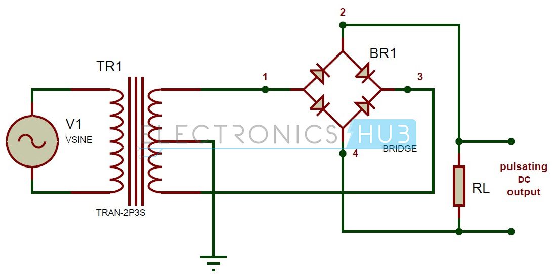
The first method makes use of a centre tapped transformer and 2 diodes. The efficiency of the full wave rectifiers is 812. Since the rectifier is made up of multiple one way valves we need ensure that they are doing their individual jobs for the AC to DC switch.
The ammeter should read zero till the voltmeter reaches 1275 volts. Full Wave Rectifier Diagram Full Wave Rectifier Theory. The following formula gives the peak factor of the full wave rectifier.
The yellow is a feed to the headlights AC through a switch and the green connects to the diode rectifier when the headlights are not on and the yellow and green connect together when the headlights are on. The brown wire is the signal input from. The horn signal is pressed in to activate the horn so in the diagram if we imagine the button pressing into and making contact with the two wires we know that is how the circuit will be completed.
Iac Idc x 106. CHOKE INPUT FILTER Special choke must be used FULL WAVE. The form factor of the full wave rectifier is calculated using the formula.
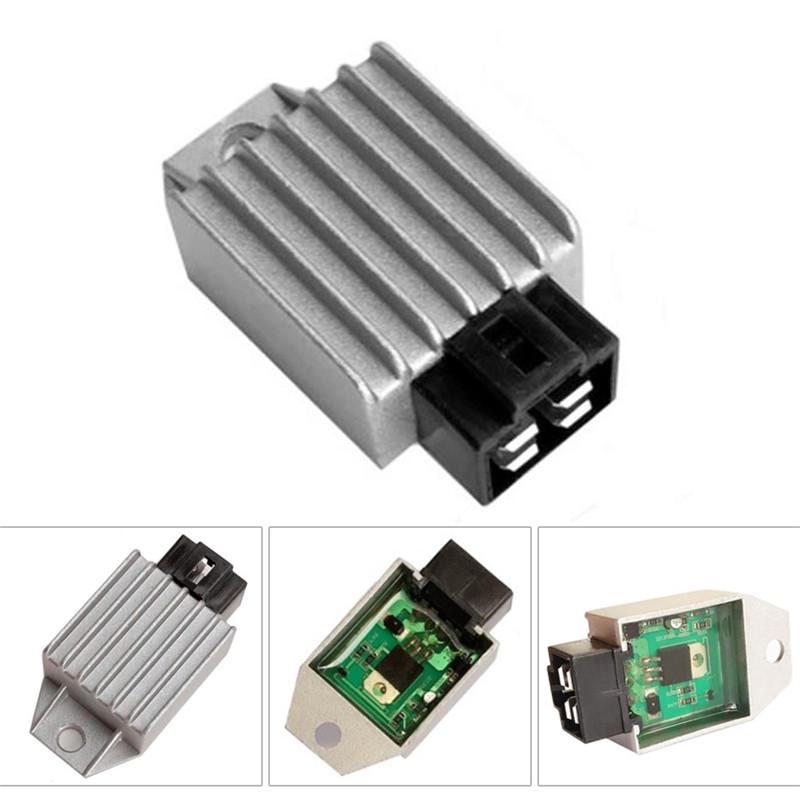
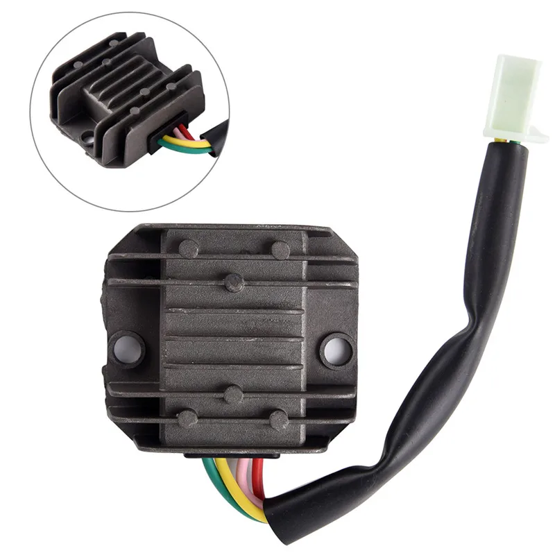
Pac Pdc x 144. 2 yellow wires AC inputs whitered DC output blackyellow DC - output and a brown. Do NOT breathe the smoke from a failing rectifier.
Selenium Full-Wave Bridge Rectifier Testing Drawn by Jon Pardue 2007 Updated 2013 Selenium Full-Wave Rectifiers 3-wire Ground connection Earth connection - minus battery terminal Negative battery terminal Chassis ground Cathode Warning. This process of converting both half cycles of the input supply alternating current to direct current DC is termed full wave rectification. Yamaha twins DS7 R5 RD250 RD350 XS650 original equipped with a separate regulator and rectifier This is an updated version fixing.
The voltmeter should read 135-153 volts. 23 The Center-Tapped Transformer Rectifier 11 24 A Basic Half-Wave Controlled Rectifier 12 25 A Basic Full-Wave Controlled Bridge Rectifier 13 26 Circuit Modes 15 27 Possible Output Voltage waveform For SCR Bridge 15 28 The Three Phase Full-Bridge Uncontrolled Rectifier 17. With sele-nium rectifiers no filament power is required.
Iac Idc x 065. The corresponding voltage across load is 1243V because the average output voltage of the discontinuous waveform can be seen in the digital multi-meter. Tube rectifiers need filament power to ther-mally stimulate electron flow.
KZ400 and KZ750 twins late model with permanent magnet alternator Pre 1978 Honda singles and twins. Full wave rectifier is the semiconductor devices which convert complete cycle of AC into pulsating DC. A multiple winding transformer is used whose secondary winding is split equally into two halves with a common center-tapped connection.
Configuration results in each diode conducting in turn when its anode terminal is positive with respect to the transformer center point C. Full Wave Rectifier Circuit Without filter. Honda SOHC fours up to 1978.
The supply is then applied across the rectifier circuit as below. CHOKE INPUT FILTER Special choke must be used BRIDGE. Vac Vdc x 222.
For example on a 1981 Kawasaki KZ440 there are 5 wires going to the OE part. In England its rated as lethal. Built in relay activates switched 12V DC output line only when engine is running with adjustable shut-off delay.
Trail Techs RegulatorRectifier is not an. The 5Y3 for exam-ple requires 5 volts at 2 amperes to heat its fila-ment. Full Wave Rectifier Circuit With Filter.
2 yellow wires AC inputs whitered DC output blackyellow DC - output and a brown wire. Set your multi-meter to read resistance. Motorcycle turn signals are used by pushing the piece left and right so knowing that we can imagine the center piece on the diagram to activate either side of the switch.
The lower efficiency drawback of half wave rectifier can be overcome by using full wave rectifier. Many Ricks Motorsport Electrics RectifierRegulators eliminate what is commonly referred to as a signal wire on original equipment OE pieces. Wire connection for use with most machines.
1 Full wave rectifier 1 Dropping resistor 1 Class 7001 Type K DC relay For 30 applications consult factory. Vac Vdc x 111. Full wave rectifier can be constructed in 2 ways.
Custom wiring diagrams using Oregon motorcycle Parts regulatorrectifier units. The rectification efficiency of the full-wave rectifier can be obtained using the following formula. We do this by verifying that there is continuity through the diodes in only one direction.
Unlike half wave rectifiers which uses only half wave of the input AC cycle full wave rectifiers utilize full wave. That means that 10 watts must be furnished and dissipated as heat in order to rectify enough DC to supply a 10 or 20 watt amplifier. In this circuit we use two diodes one for each half of the wave.
For example on a 1981 Kawasaki KZ440 there are 5 wires going to the OE part. Add voltage code to the end of the Type No.

Smoothing Capacitor For Scooter Regulator High Constant Current Drawn Electrical Engineering Stack Exchange
Full Wave Bridge Rectifier Output Waveform Circuit Boards

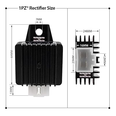
Buy 1pz Fw1 R01 4 Pin 12v Full Wave Motorcycle Regulator Rectifier For 50cc 70cc 90cc 110cc 125cc 150cc Gy6 Engine Moped Scooter Atv Online In Indonesia B088gx8pc2
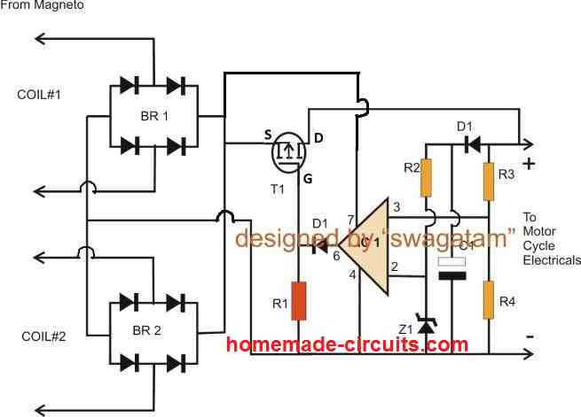
Motorcycle Mosfet Full Wave Shunt Regulator Circuit Homemade Circuit Projects
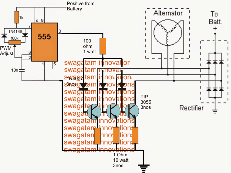
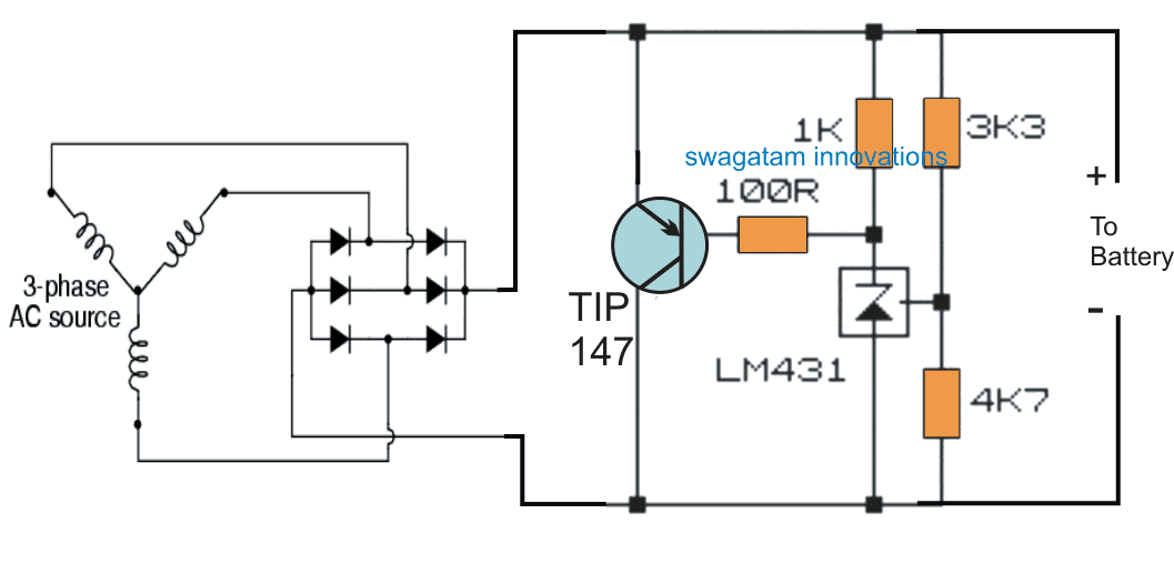
3 Phase Motorcycle Voltage Regulator Circuits Homemade Circuit Projects

What S The Point Of The Black Wire On A 5 Wire Full Wave Regulator Rectifier Adventure Rider
Full Wave Bridge Rectifier Output Waveform Circuit Boards

Recitifer Regulator Signal Wires Rick S Motorsport Electrics Blog And More
Buy Motorcycle Voltage Regulator Rectifier 4pin For Gy6 50cc 125cc 150cc Scooter At Affordable Prices Free Shipping Real Reviews With Photos Joom

Your Bike S Charging System Regulator Rectifiers And Alternators
Schematic Diagram Of Motorcycle Cdi And Motorcycle Regulator Rectifier Schematic Best Of The Best Voltage Regulator Diagram Motorcycle
Universal 4 Wire Full Wave Motorcycle Regulator Rectifier For 12v Dc Bike Quad Motorbike Ingition Aliexpress

Solusi Battery Cara Mudah Membuat Kiprok Fullwave Regulator Pengisian Aki Pengisian Jurnal Ilmiah Listrik
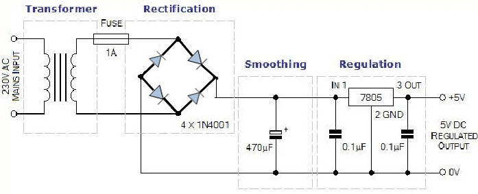
Diagram Ac To Dc Bridge Rectifier Circuit Diagram Full Version Hd Quality Circuit Diagram Tuataradiagram Patriziaprestipino It
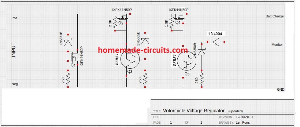
Motorcycle Mosfet Full Wave Shunt Regulator Circuit Homemade Circuit Projects
Diagram Dirt Bike Voltage Regulator Rectifier Wiring Diagrams Full Version Hd Quality Wiring Diagrams Ediagramming Stefanomoriggi It


Pin On Superwowchannels

4 Wire Full Wave Motorcycle Regulator Rectifier 12v Dc Bike Quad Scooter Ebay
3 Phase Motorcycle Voltage Regulator Circuits Homemade Circuit Projects